Focal Mechanisms

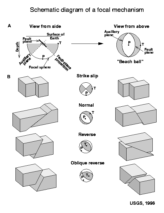
Seismologists refer to the direction of slip in an earthquake and the orientation of the fault on which it occurs as the focal mechanism. They use information from seismograms to calculate the focal mechanism and typically display it on maps as a "beach ball" symbol. This symbol is the projection on a horizontal plane of the lower half of an imaginary, spherical shell (focal sphere) surrounding the earthquake source (A). A line is scribed where the fault plane intersects the shell. The stress-field orientation at the time of rupture governs the direction of slip on the fault plane, and the beach ball also depicts this stress orientation. In this schematic, the gray quadrants contain the tension axis (T), which reflects the minimum compressive stress direction, and the white quadrants contain the pressure axis (P), which reflects the maximum compressive stress direction. The computed focal mechanisms show only the P and T axes and do not use shading.
These focal mechanisms are computed using a method that attempts to find the best fit to the direction of P-first motions observed at each station. For a double-couple source mechanism (or only shear motion on the fault plane), the compression first-motions should lie only in the quadrant containing the tension axis, and the dilatation first-motions should lie only in the quadrant containing the pressure axis. However, first-motion observations will frequently be in the wrong quadrant. This occurs because a) the algorithm assigned an incorrect first-motion direction because the signal was not impulsive, b) the earthquake velocity model, and hence, the earthquake location is incorrect, so that the computed position of the first-motion observation on the focal sphere (or ray azimuth and angle of incidence with respect to vertical) is incorrect, or c) the seismometer is mis-wired, so that "up" is "down". The latter explanation is not a common occurrence. For mechanisms computed using only first-motion directions, these incorrect first-motion observations may greatly affect the computed focal mechanism parameters. Depending on the distribution and quality of first-motion data, more than one focal mechanism solution may fit the data equally well.
For mechanisms calculated from first-motion directions as well as some methods that model waveforms, there is an ambiguity in identifying the fault plane on which slip occurred from the orthogonal, mathematically equivalent, auxiliary plane. We illustrate this ambiguity with four examples (B). The block diagrams adjacent to each focal mechanism illustrate the two possible types of fault motion that the focal mechanism could represent. Note that the view angle is 30-degrees to the left of and above each diagram. The ambiguity may sometimes be resolved by comparing the two fault-plane orientations to the alignment of small earthquakes and aftershocks. The first three examples describe fault motion that is purely horizontal (strike slip) or vertical (normal or reverse). The oblique-reverse mechanism illustrates that slip may also have components of horizontal and vertical motion.
Please send comments or suggestions regarding this page to Dave Oppenheimer.
