3d~def is a three-dimensional boundary-element model that allows the calculation of stresses, strains, and displacements within and on the surface of an elastic half-space; there is no bottom to the model. The power of the model comes from the ability to a) solve for a variety of deformation quantities on a variety of faults and planes simultaneously, and b) to drive the deformation in relatively realistic (and therefore potentially complex) ways.
The principal difference between boundary-element models and standard dislocation models is that in the former the slip values, or the magnitudes of the dislocation components, are treated as unknowns that are solved for in order to minimize the strain energy in the medium while satisfying stress or displacement boundary conditions on each dislocation surface.
The minimization of strain energy is physically reasonable assuming that fault slip is the primary means of relaxing strains in the upper crust. Boundary-element models explicitly account for the interaction among faults whereas dislocation models generally ignore both fault interaction and the minimization of strain energy.
Boundary-element = constant slip surface
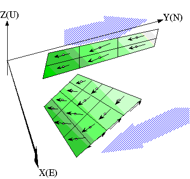
Minimize the global shear-strain energy
Rectangular, planar dislocations in a uniform elastic half-space are referred to as elements. Not all planar dislocations need be faults; e.g., they may also be used as displacement boundaries or as the surface of a magma chamber.
Displacements of elements may be driven by a variety of ways, including the specification of a regional stress, strain, or displacement gradient tensor, by specifying far-field boundary conditions, or by specifying displacements or stresses on any other elements. These methods can be combined. For example, we might drive a system of fault-elements by a regional strain tensor and by imposing slip on one of the model faults, leaving the remainder to slip as they will, constrained only by the requirement that the shear-strain energy is minimized. Go here for details on driving the models, and here to check some of the pitfalls.
![]() During any deformation, lines and planes will be
rotated. Such rotations are properly modeled here only for the
symmetric (pure shear) part of the displacement gradient tensor. But,
if you are modeling long-term deformation, where there is an implicit
repeat of the elastic deformation, then bear in mind that the faults
specified in the input file are not rotating as they should be.
During any deformation, lines and planes will be
rotated. Such rotations are properly modeled here only for the
symmetric (pure shear) part of the displacement gradient tensor. But,
if you are modeling long-term deformation, where there is an implicit
repeat of the elastic deformation, then bear in mind that the faults
specified in the input file are not rotating as they should be.
Some general definitions:
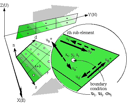
Deformation at any observation point (x,y,z) is the superposition of the deformation due to slip on each of a set of planar dislocations plus some uniform deformation field. The complete deformation field is fully described by the displacement vector,
![]()
the displacement gradient tensor,
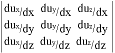
and the material constants, Poisson's ratio and Young's modulus. The stress, strain, and rigid body rotation tensors can all be derived from the displacement gradient tensor and the material constants.
The components of relative displacement (fault slip) in the strike, dip, and normal directions respectively, on each element are
![]()
Negative superscripts refer to the absolute displacement of the footwall, positive to the absolute displacement of the hangingwall.
Solving the numerical problem:
The interaction of one element (a dislocation or fault segment) with other elements and with the background deformation is modeled by solving a set of linear equations formulated as follows.
1) For each element, a set of displacement and/or stress boundary conditions is specified at a point at the center of the element. The figure below illustrates this for stress boundary conditions and two elements:
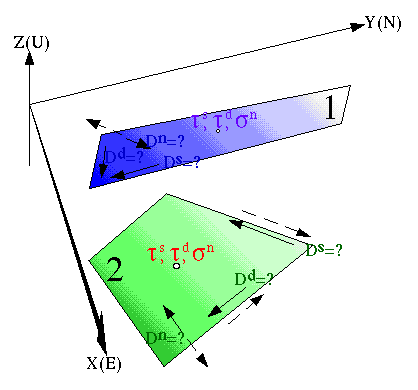
![]() Note that boundary conditions are specified only
at the center point of each element; they do not apply to the entire
surface of the element. More accurate results will be obtained by
sub-dividing elements, but at the price of computational time and
memory requirements.
Note that boundary conditions are specified only
at the center point of each element; they do not apply to the entire
surface of the element. More accurate results will be obtained by
sub-dividing elements, but at the price of computational time and
memory requirements.
2) We write a set of linear equations like this,
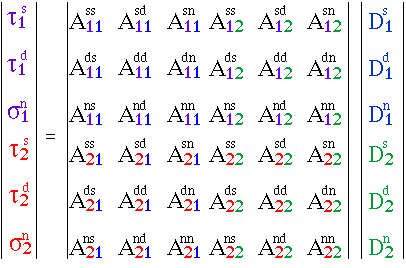
ts, td, sn are the tractions on each element in the strike and dip directions and the tensile (normal) stress, respectively. The so-called influence coefficients (Green's functions) (the A's above) are calculated using routines provided by Okada [1992]. Displacement boundary conditions may be written in an analogous fashion using the appropriate Green's functions.
3) The unknown relative displacement components (the D's) are solved for using a simple matrix inversion.
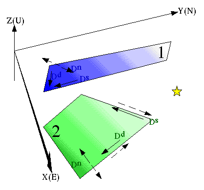
4) Once the relative displacements are found, the deformation field at any point in the medium (e.g., yellow star below) is calculated analytically.
![]()