![]()
![]()
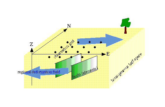
Element - an element is a planar dislocation that may be used as a fault plane, a dike, a boundary of displacement, or almost anything that is planar.
Subelement - an element may be (and usually is) divided into smaller elements, or subelements. The numbering or ordering system is as shown below, looking down the positive z-axis (planar coordinates) or from the hangingwall if that's clearer.
1, 3 |
2, 3 |
3, 3 |
1, 2 |
2, 2 |
3, 2 |
1, 1 |
2, 1 |
3, 1 |
![]() Bear in mind that this ordering is not the same as
that which is output in vector format.
Bear in mind that this ordering is not the same as
that which is output in vector format.
Inspection plane - is the plane of coordinates to which output results are referred. For example, it is common to want displacements of the Earth's surface, so the inspection plane might be defined like this:
-10 10 0 90 0 20 20
where the first three numbers refer to the origin of the plane (in either global or in-plane coordinates, in this case, global), which is therefore at 10 km west and 10 km north of the coordinate origin and at the surface. The next two numbers are the strike (90) and dip (0) of the plane, and the last two refer to the along-strike and along-dip distances. Thus, this plane is flat and runs 20 km to the east and 20 km to the south of its origin. You can see that the specification of the inspection plane is the same as it is for any element.
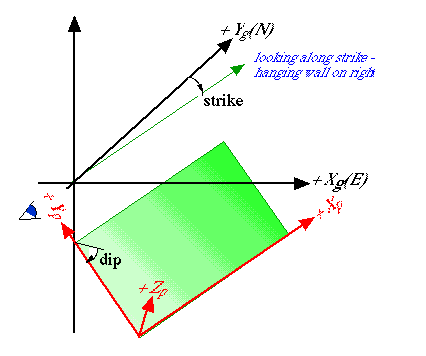
Coordinate systems: we use three difference coordinate systems in 3d~def, each right-handed and shown in the table and figure below. The local system is used only inside the program, so the casual user can ignore it.
| system | X | Y | Z |
| global | east | north | up |
| planar (in-plane) | along strike | up-dip | plane-normal into hangingwall |
| local | along strike | horizontal, normal to strike and into footwall | up |
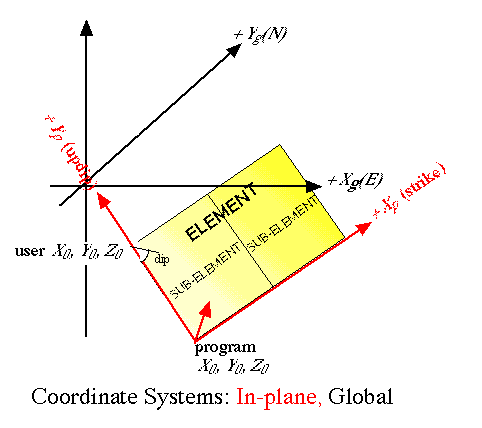
Footwalls, hangingwalls, and relative displacements: the footwall lies under the hangingwall, so that a hangingwall moves up and over the footwall across a reverse fault, and it slides down and to a level below the footwall across a normal fault. If you use the right-handed convention (which we do in 3d~def) , then the hangingwall lies to the right of the strike direction.
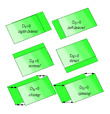
Relative displacements across elements always refer to the motion of the hangingwall (HW) with respect to the footwall (FW). Thus, a negative shear displacement means that the HW has moved opposite to the strike direction (since the strike is the positive axis), which yields a right-lateral sense of motion. Likewise, a positive displacement in the dip direction indicates a reverse sense of motion. Here are some figures to make it all clear.
Units are given in the table below:
| feature | units |
| element dimension | km |
| element displacements | cm |
| output displacements | cm |
| stress | same asYoung's modulus |
| strain | none |
Boundary conditions: these are the conditions applied to the central points of elements in the model input. They may be specified in terms of relative displacement, shear or normal stress, orientation of that stress, and absolute displacement. "code" numbers in the input file indicate which combination of conditions are being used. Because boundary conditions are applied to a plane, they are divided into components along the planar coordinates (strike, dip, and normal).
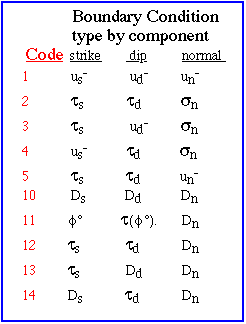
See driving the deformation for examples and details.
![]()